Overview
Snap PPK is an adapter kit to connect an
Emlid
Reach GNSS receiver [not included] to a Phantom 4 Pro/Advance. The kit snaps on in seconds to your Phantom
4 Pro - without any modifications. It is easily removed so you can still
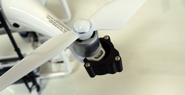
use your travel case. The front LEDs on a Phantom 4 Pro blink each time
a picture is taken. A phototransistor detects the blink and a time mark
is recorded in the Reach's log file. The time marks are extracted and
combined with the pictures as precision geotags. Accuracy is further
improved by setting the Phantom on a GCP target and taking a picture
while stationary. This position is free from shutter timing errors,
lever-arm errors, and camera calibration errors.
SnapPPK currently does
NOT work with Reach M2. Its power
requirements are 3 times higher than Reach M+. We are looking for a
solution now.
Requirements
- Phantom 4 Pro/Advance [Not Phantom 4
original]
- Emlid Reach M+ & Tallysman antenna [Not included.
Order from
Emlid]
- RINEX capable base receiver
- Tuffwing Snap PPK kit
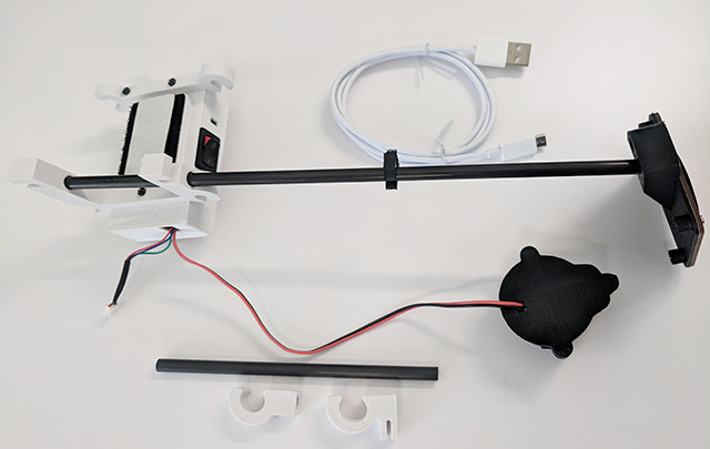
How it works
- Main body with ground plane, Velcro and
- Cross brace
- Zip ties for attaching antenna and Reach M+.
- Micro USB cable for charging battery
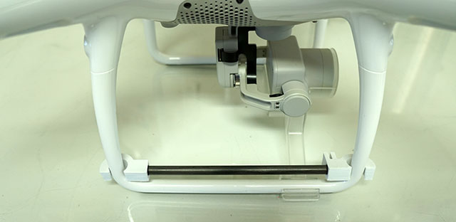
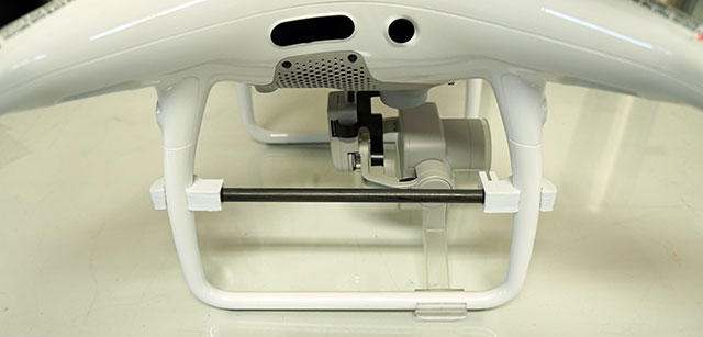
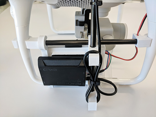
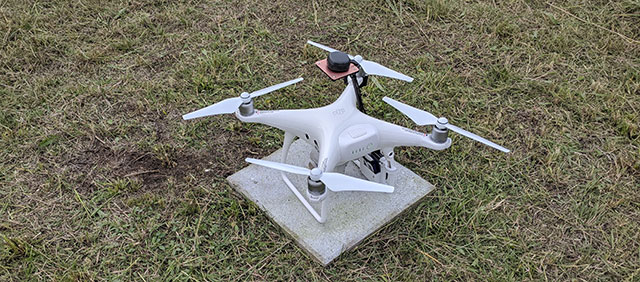
- Install the cross bar at the bottom of the right landing gear.
- Slide the cross bar up.
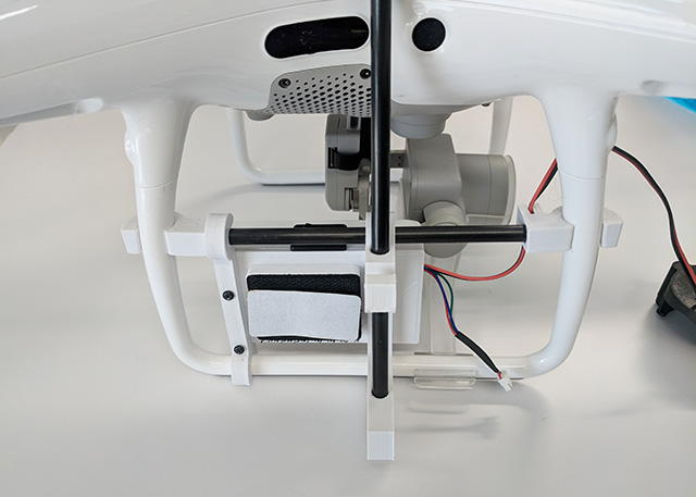
- Snap in the battery/mast holder. Slide to left so the antenna mast is between the side sensors.
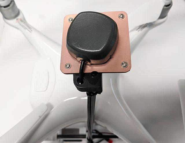
- Install your Tallysman antenna on the ground plane using Velcro and zip ties as shown.
- Wrap the antenna wire around the mount and zip tie in place as shown.
- Install the your Reach using Velcro. Connect the antenna to
ANT and the time mark/power cable to C1.
- Slide on the LED cover.
- Snap LED cover into place. You do not need to remove the screws.
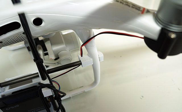
- Tuck the LED cover wire into the groove.
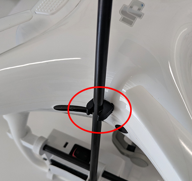
- Position vibration dampener as shown.
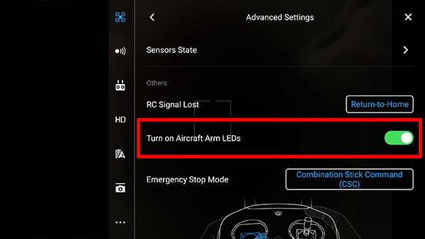
- Go to DJI Go > Advanced Settings and enable Turn on
Aircraft Arm LEDs.
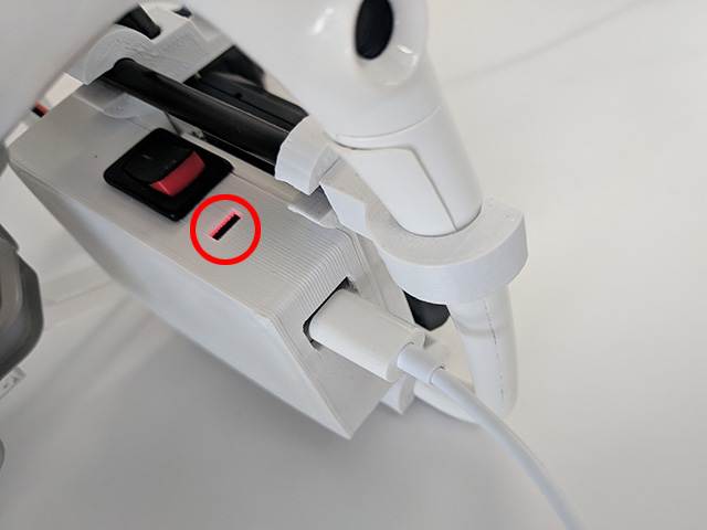
- Connect the MicroUSB cable to the port as shown. Power with any
5 volt USB charger/laptop.
- Blinking LED indicates battery not fully charged.
- Solid LED indicates full battery.
- Blinking LED while no USB cable connected indicates low
battery.
- Install the
ReachView
App on your Android or IPhone.
- Disable Mobile Data on Android phones while using ReachView.
- Power your Reach module.
- Go to your mobile device's Wi-Fi settings and connect to the Reach hot spot.
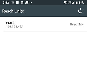
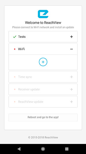
- Start ReachView App and select your Reach Module.
- Select + to add your Wi-Fi network to your Reach Module.
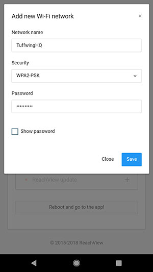
- Enter your Wi-Fi network information.
- Reboot your Reach.
- Reconnect your mobile device to your Wi-Fi network.
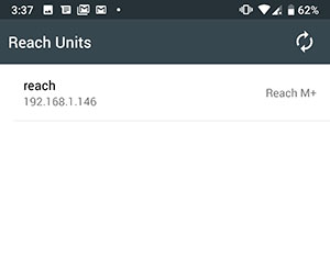
- Refresh ReachView. Your Reach Module will now have a local IP address (192.168.1.###)
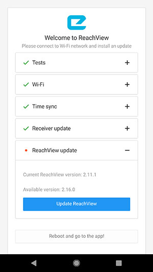
- Update ReachView (the Reach M+ firmware). Reboot when complete.
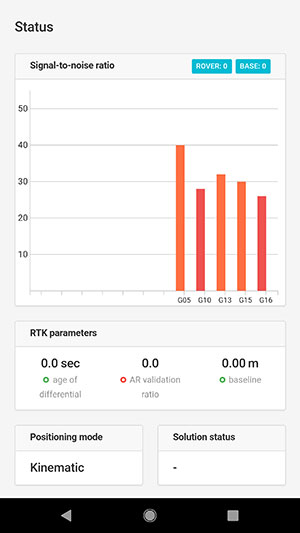
- Refresh ReachView App and connect to the Reach Module. You can now see status, download logs and make configuration changes.
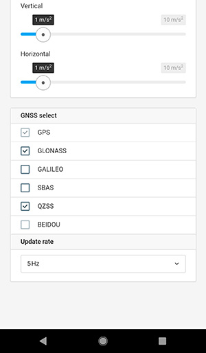
- Go to ReachView > RTK Settings and set
GNSS select to GPS, GLONASS, and QZSS. Set
Update rate to 5Hz. Do this for both Rover and Base.
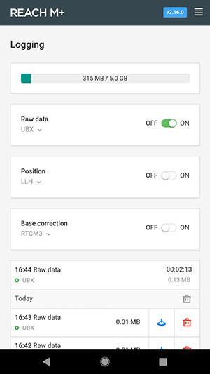
- Go to ReachView > Logging and set Raw
data to
UBX.
- Create a photographic mission using any flight planning
software.
- Power up and power down the Reach in this order:
- Power Phantom 4 Pro and remote transmitter.
- Power Reach
- Fly mission
- Collect ground control
- Power down Reach
- Power down Phantom
Note: the Reach records a time mark when
the LEDs are off. This sequence avoids mismatched geotags
and photos.
- Mark a ground control point [one or more] by using the Shutter button on the Phantom remote to take a
picture directly over a target or landmark.
After you fly you will need to download the log files that were accumulated.
- Use ReachView to your Reach Module [and/or Reach base].
- If connected to your local Wi-Fi network - Start ReachView App and connect to your Reach
Module.
- If in the field (not connected to your local Wi-Fi) - Go to your mobile device's Wi-Fi
settings and connect to the Reach hot spot. Then start the ReachView App and connect to your Reach Module.
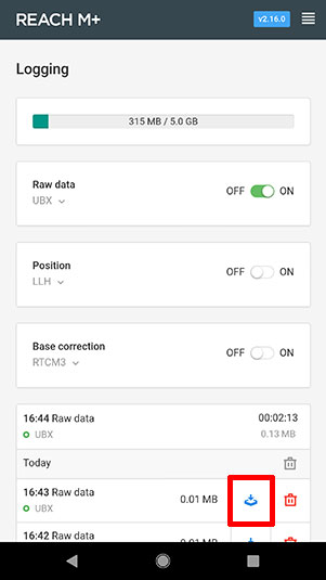
- Select Logging from the ReachView menu.
- Use the download link to download the UBX file that was
accumulated during the flight.
Note: You can toggle the On/Off button to break the
UBX file and make it downloadable.
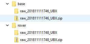
- Find the UBX file in your mobile device's file system and email
it to yourself. Then retrieve it on your PC for post processing.
- The UBX file will be in a .zip folder. Save and unzip in a folder appropriately named Base or Rover.
Convert UBX files to RINEX
- Download
RTKLIB from Emlid.
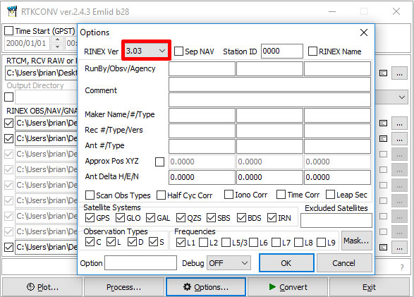
- Start rtkconv.exe [RTK Convert]
- Select Options > RINEX Ver > 3.03.
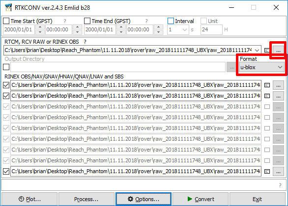
- Select Format > u-blox.
- Select ... and load your Rover or Base .bx file.
- Select Covert to create RINEX files [.obs and
.nav]
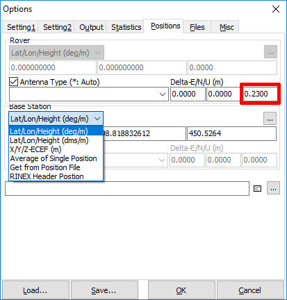
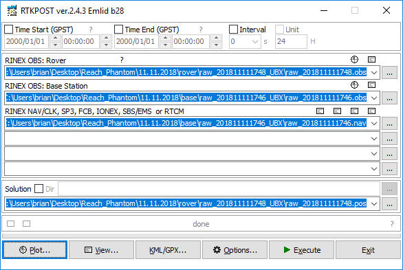
- Start rtkpost.exe [RTK Post], select Options and configure the following:
- Select Antenna Type and enter .23 [m] to correct antenna height from
camera sensor. Lever-arm error is not accounted for and
must be corrected with ground control. Select OK.
-
Select Lat/Lon/Height for known base
position or RINEX Header Position for a CORS base
or relative precision using a Reach base.
- Use ... to select the Rover
and Base Station .obs files. Select the Base .nav
file for the RINEX NAV/CLK
row.
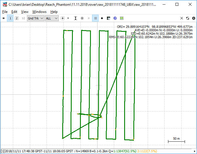
- Note location of Solution folder. Two solution files will be
created. .pos is the rover path and _events.pos contains the time
mark locations.
- Select Execute to process the files and create
a solution.
- Select Plot to to launch RTK Plot and view your
corrected rover path.
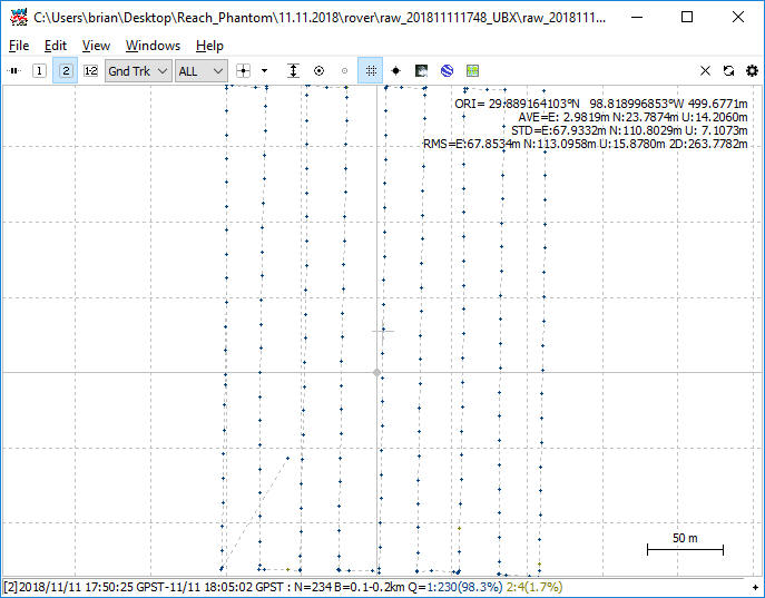
- Select File > Open Solution 2 and open your _events.pos file. This contains your time marks.
- Use the 1 2 buttons at the top left to toggle between Solution 1 and Solution 2.
- Start Microsoft Excel and select File > Open.
- Navigate to the folder that contains the _events.pos file.
- Change Files of Type: to All Files (*.*)
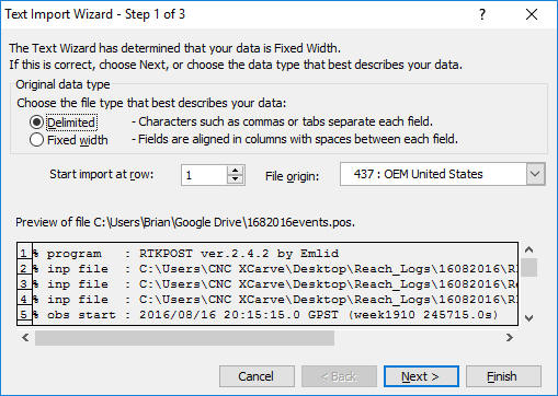
- Select the .pos file and click Open.
This will start the Text Import Wizard.
- Select Delimited, then Next.
- Select Space, then Finish.
- Select the latitude, longitude, and height data.
Note height of last time mark. 100m below others. This is a
ground control point.
Note Column Q is Fix or Float status
- Copy the time marks [except the ground control points] and paste them into
Notepad and save as a geotags.txt.
- Subtract .04 [4cm] from the height of the ground control time marks. The
antenna height is 27cm above the ground. 23cm was already subtracted during
post processing for the geotags. Now an additional 4cm subtracted to reach
the ground. Copy and paste the ground control points into Notepad and save
as GCP.txt.
- Open your picture folder and remove any pictures that are
not part of the mission.
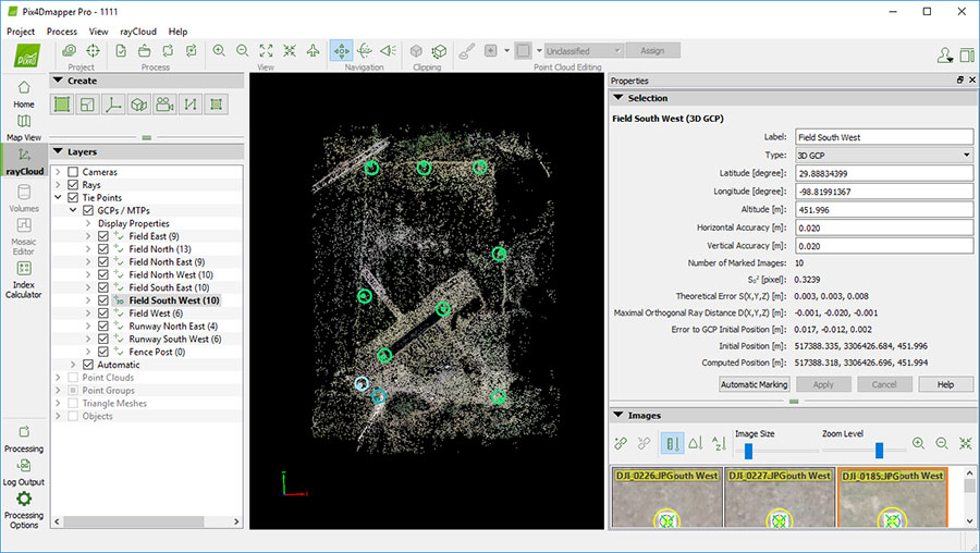
Note: You should have a the same amount of
pictures and geotags. If you don't have a match you can import
into Pix4D to determine which picture/geotags are mismatched by
looking at the initial and computed positions of the pictures in
the rayCloud editor.
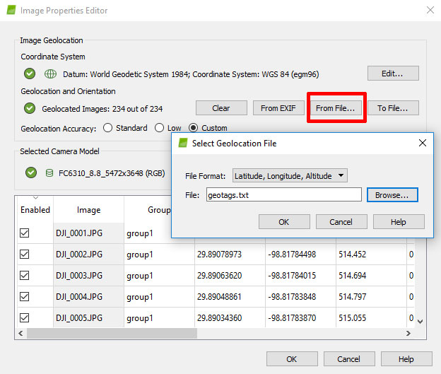
- Create a new project in Pix4D and select your pictures.
- Select From File > File Format > L,L,A.
- Browse to geotag.txt and press the
OK button.
- Select Custom Geolocation Accuracy.
- Right click in the Acuracy Horz [m] box and
change the value to .05. Do the same for Vert [m].
- Click OK.
- Process the 3D Map.
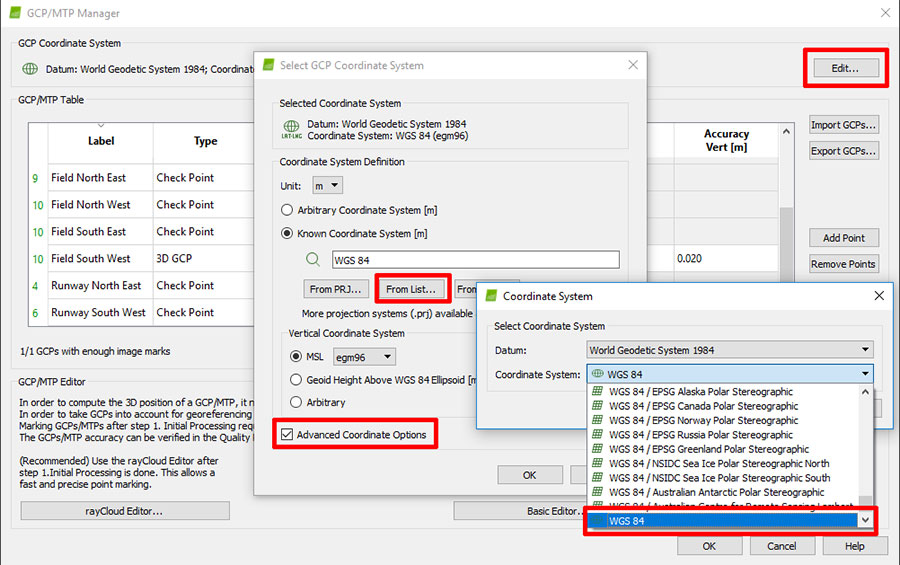
- Set the GCP coordinate system. Go to Project > GCP/MTP Manager. Select
Edit > Advanced Coordinate Options > From List >>then select WGS 84.
Note: Go to the bottom of the list and select
"WGS 84" only, not any of the zoned.
- Import the GCP file.
- Select Import GCPs. Browse to GCP.txt.
- Set Type to 3D GCP or Check Point.
- Press OK.
-
Mark the
GCP and Check Points in the rayCloud editor.
- Click the Apply button.
- Select Process > Rematch and Reoptimize.
- Select Generate Quality Report.
|