Overview
Do the following in sequence to build your UAV Mapper airframe.
- Kit contents
- Building materials
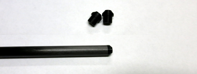
- Glue spar tips
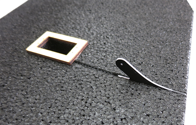
- Install the control horns
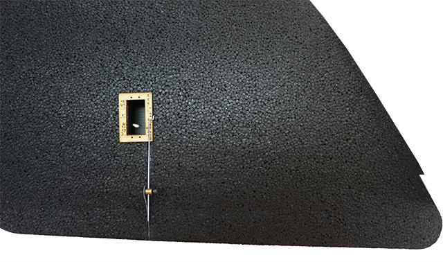
- Install the
servo quick connects
- Install the winglets
- EPP wing set and body
- Camera mount
- Control horns (2)
- 10mm x 31” carbon fiber tube - center wing spar (1)
- 10mm x 28” carbon fiber tube – leading edge wing spars (2)
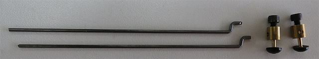
- Control rod with Z bend (2)
- Control rod quick connect (2)
- 3/32" Imperial hex key for quick connect
- 3mm x 8mm motor mount screws (4)
- Servo extensions included with airframe
| From |
Extension Length |
To Peripheral |
| RC |
30cm |
SBUS out from receiver |
| SB |
30cm |
RSSI out from receiver |
| MAIN OUT 1 |
30cm |
Right wing servo |
| MAIN OUT 2 |
15cm |
Left wing servo |
| AUX OUT 4 |
15cm |
Hot shoe |
| AUX OUT 2 |
15cm |
Camera trigger |
| AUX OUT 1 |
15cm |
Parachute |
| L9R |
15cm male to male |
RSSI |
| L9R |
20cm male to male |
SBUS |
| Servo - right wing |
15cm |
body |
| Servo - left wing |
15cm |
body |
- Hot glue.
- Medium CA. Foam safe NOT required.
- CA activator
-
Use CA to glue the center spar tips to the spar.
- Drip medium CA into the control horn gap.
- Quickly press the control horn into the gap.
- Spray with CA accelerator.
- Do both sides.
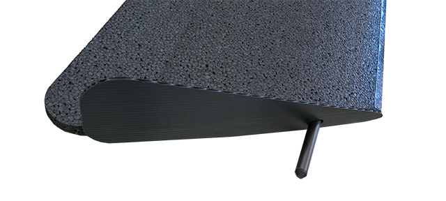
- Insert the pushrod quick connect on the tip side of the wing as shown. Press the black nylon washer on with pliers.
- Insert the leading edge spar backwards so you can align the
winglet.
- Apply hot glue the wing tip.
- Slide winglet over spar and align bottom edge, then firmly press together until
hot glue cools. Do both sides.
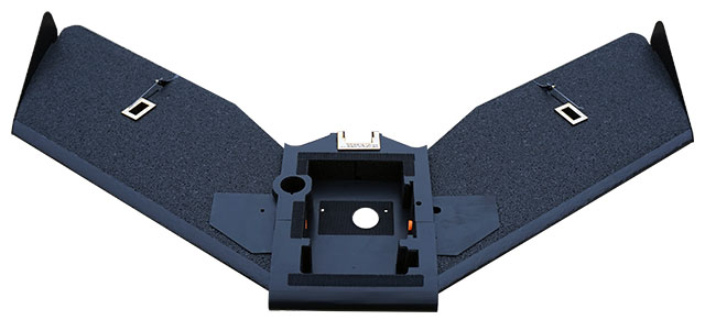
Complete Airframe
Errata, kudos, brian.christal@gmail.com
Continue to UAV Mapper Electronics and Pixhawk Installation Guide >>
|