Overview
Do each of the steps below in sequence to install
your motor, servos, ESC, and Pixhawk.
- Electronics Required when DIY
building a UAV Mapper airframe
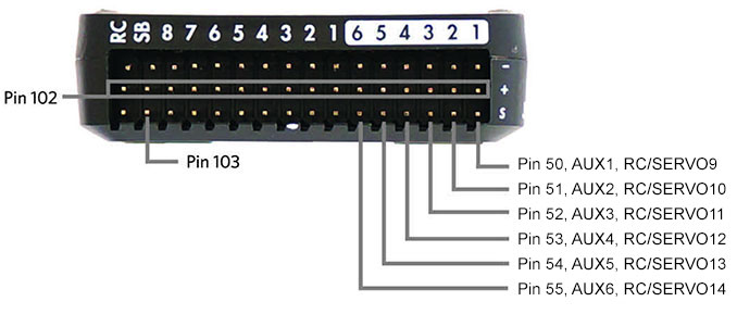
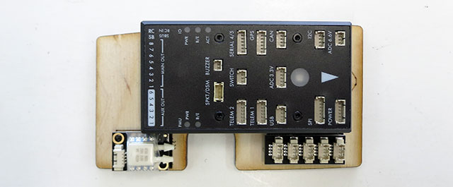
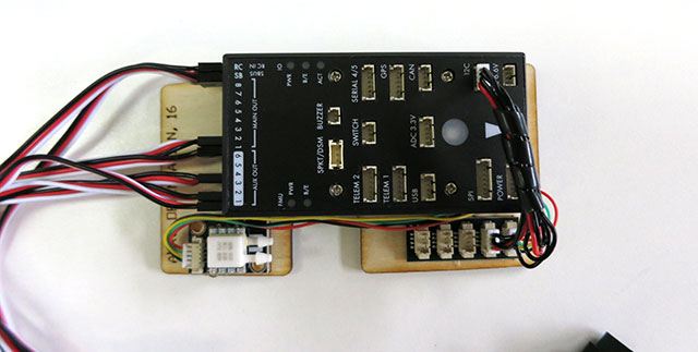
- Pixhawk pin
out and accessory locations
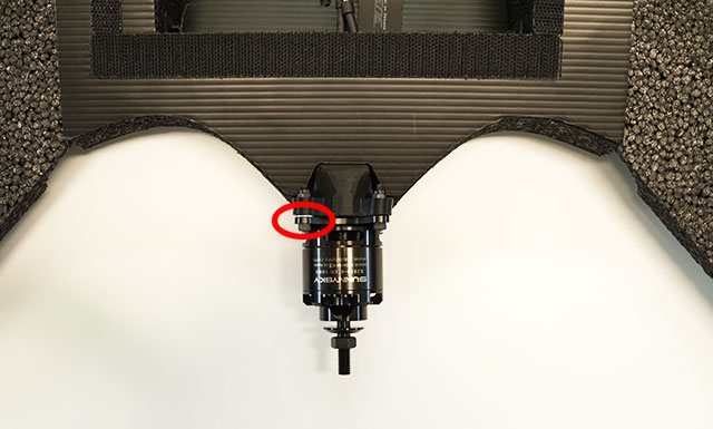
- Install the motor
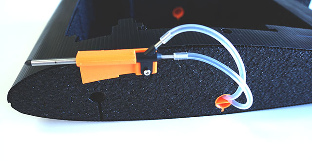
- Install the pitot tube
- Install the parachute
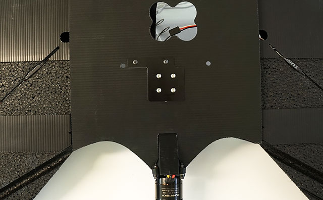
- Mount Pixhawk, airspeed sensor, and I2C splitter
- Install GPS/Compass
- Mount the telemetry radio
- Install Pixhawk and make final connections
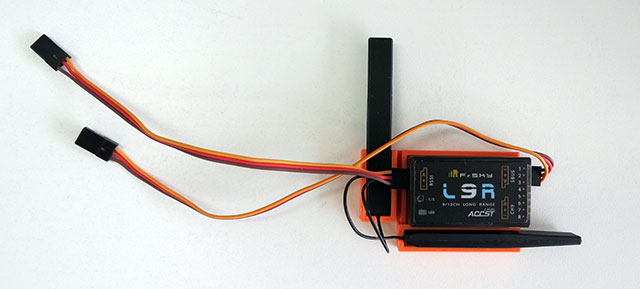
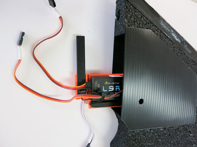
- Install the FrSKY L9R RC receiver
- Install the servos
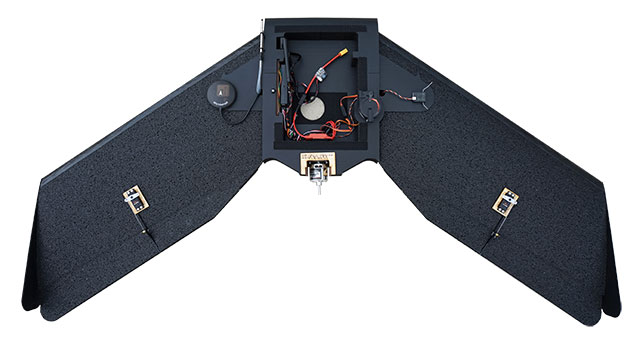
Electronics - not included with
airframe
The UAV Mapper
parameter file configured for the following accessories and positions:
- Install the X mount and prop adapter.
- Insert the 3 motor wires through rectangle opening in the bottom of the motor mount.
- Attach the motor using the supplied 16mm x 3mm screws and nuts.
- Important: Add washers to the left side of the motor mount. This
helps counteract torque roll during take off.
Danger:
Do not install the propeller until all configuration is complete.
- Slide pitot tube into mount and install screw. Cut silicone tubing in 1/2 and push through body.
- Insert the four 3mm screws (included with the parachute) into the composite plate on the bottom of the body.
- Install the parachute with the servo to the back of the body.
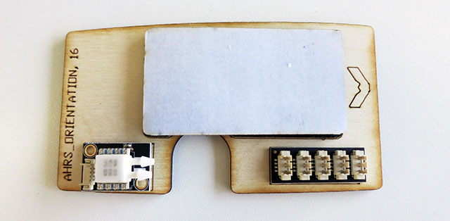
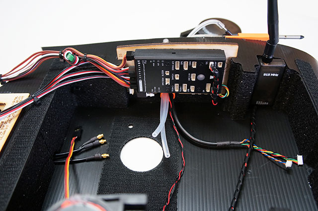
- Hot glue the airspeed sensor and I2C splitter to the Pixhawk mount board.
- Stick the loop Velcro to the back of your Pixhawk and place on board.
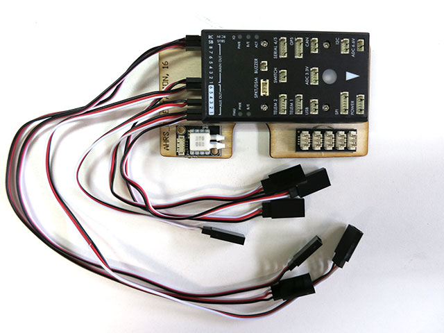
- Install the following servo extensions:
| Pixhawk |
Extension Length |
Peripheral |
| RC |
30cm |
SBUS out from receiver |
| SB |
30cm |
RSSI out from receiver |
| MAIN OUT 1 |
30cm |
Right wing servo |
| MAIN OUT 2 |
15cm |
Left wing servo |
| AUX OUT 4 |
15cm |
Hot shoe |
| AUX OUT 2 |
15cm |
Camera trigger |
| AUX OUT 1 |
15cm |
Parachute |
- Connect the I2C splitter to the I2C port on your Pixhawk.
- Connect the airspeed sensor to the I2C splitter.
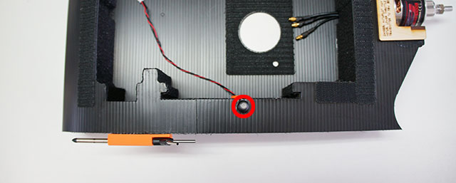
- Install the ARM button in the body.
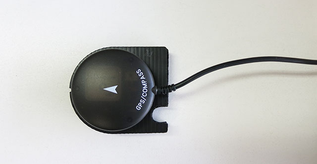
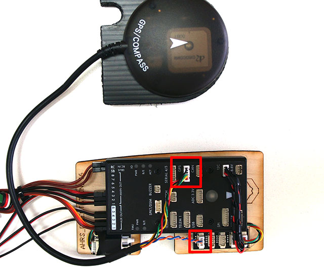
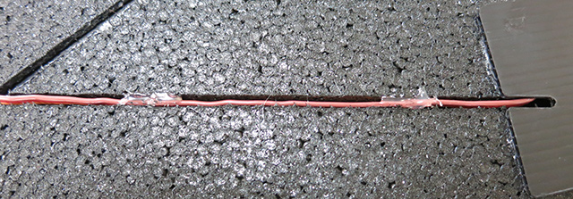
- Use the supplied Velcro to stick the GPS/Compass to the mount. Aim arrow at notch. (left)
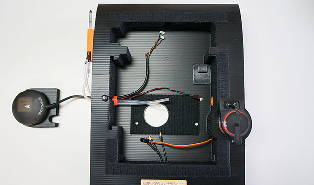
- Slide the GPS/Compass wires through the top half of the orange wire guide.
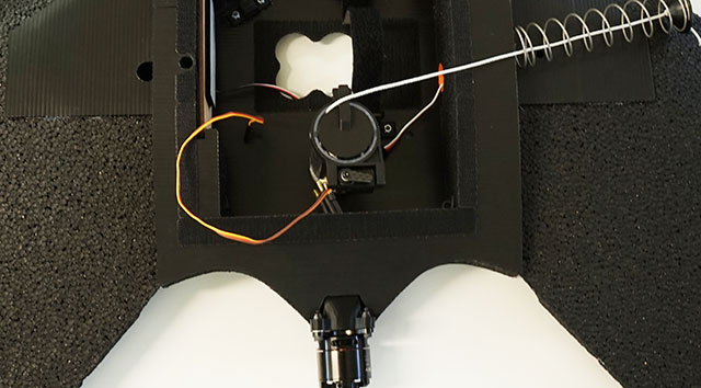
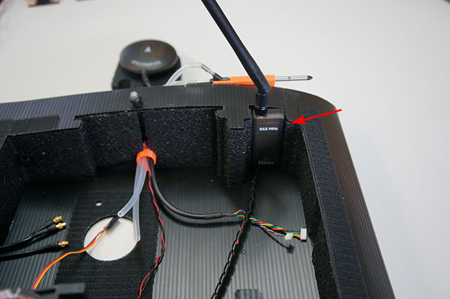
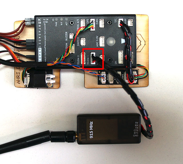
- Insert the telemetry radio into the foam cut-out.
- Slide the Pixhawk into the body.
- Plug the 6 pin connector into the GPS port on the Pixhawk. Plug the 4 pin connector into any port on the I2c splitter.
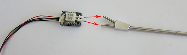
- Connect the silicone hose to the tubes as shown.
- Straight pitot tube (stagnation tube) to port further from circuit board.
- Angle pitot tube (static tube) to port closest to circuit board.
- Connect telemetry radio to TELEM 1 on the Pixhawk.
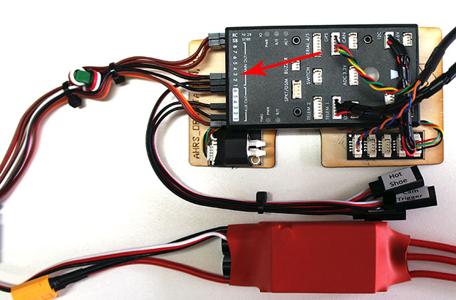
- Connect the ESC servo connector to MAIN OUT 3.
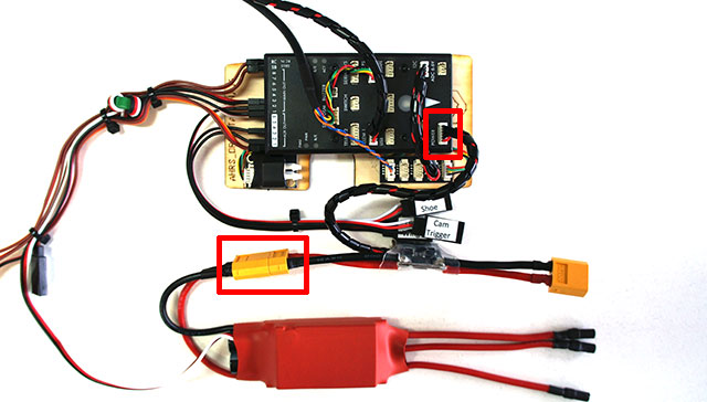
- Connect power module to ESC and Power port on Pixhawk.
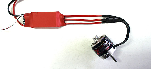
- Connect the three motor ESC wires to the motor. Connect in any order. Switch any two wires to make the
motor spin the correct direction.
- Set receiver and antennas in the receiver mount. Attach with hot glue.
- Insert the receiver into the right wing.
- Connect the SBUS wire from the L9R
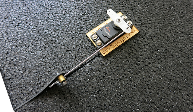
- Use needle nose pliers to push the servo wire through the hole in the bottom cover.
- Install the pushrod in the middle outside hole on the servo arm. Widen the servo arm with 1/16" drill bit so the pushrod will fit.
Note: You will center the servos later when you
configure your Pixhawk and transmitter.
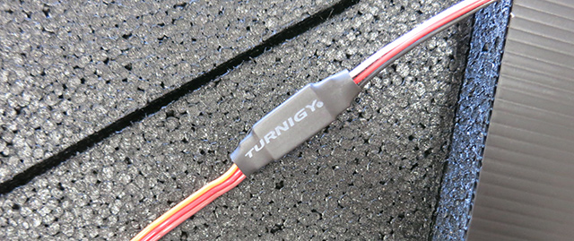
- Connect 15cm servo extensions and shrink tube (included).
Note: Install shrink tube after you push the servo wire through the bottom cover.
- Tuck servo extension into groove on wing bottom and tack with hot glue. Do not use CA as it will be too permanent.
- Install the wings on the body
- Connect the right wing servo to MAIN
OUT 1.
- Connect the left wing servo to MAIN OUT 2.
Continue to UAV Mapper
Transmitter and Pixhawk Configuration Guide >>
|